
When an engineer or contractor specifies a packaged mechanical system for the first time, the question of utility connections usually comes up late in the process. The system has been sized, the equipment has been selected, the layout has been approved, and then someone asks how many electrical connections are needed and where the piping tie-ins are. The answer to that question, and how it was handled during the design process, determines a significant portion of the installation complexity and cost.
Single-point utility connections are one of the most practical design decisions available on a packaged mechanical system. They consolidate all of the electrical, piping, and control connections from the system into defined single-point interfaces that the installation team connects in the field. Instead of running individual circuits to each component, making individual piping connections to each piece of equipment, and connecting controls wiring at each device, the installation team makes a small number of defined connections and the system is ready to start up.
That consolidation is not automatic. It is a design decision that needs to be specified before the fabrication drawings are finalized. This article explains what single-point connections are, what they consolidate, and what the specification needs to say to make sure the packaged system arrives with the connection configuration the installation team expects.
What single-point electrical connection means
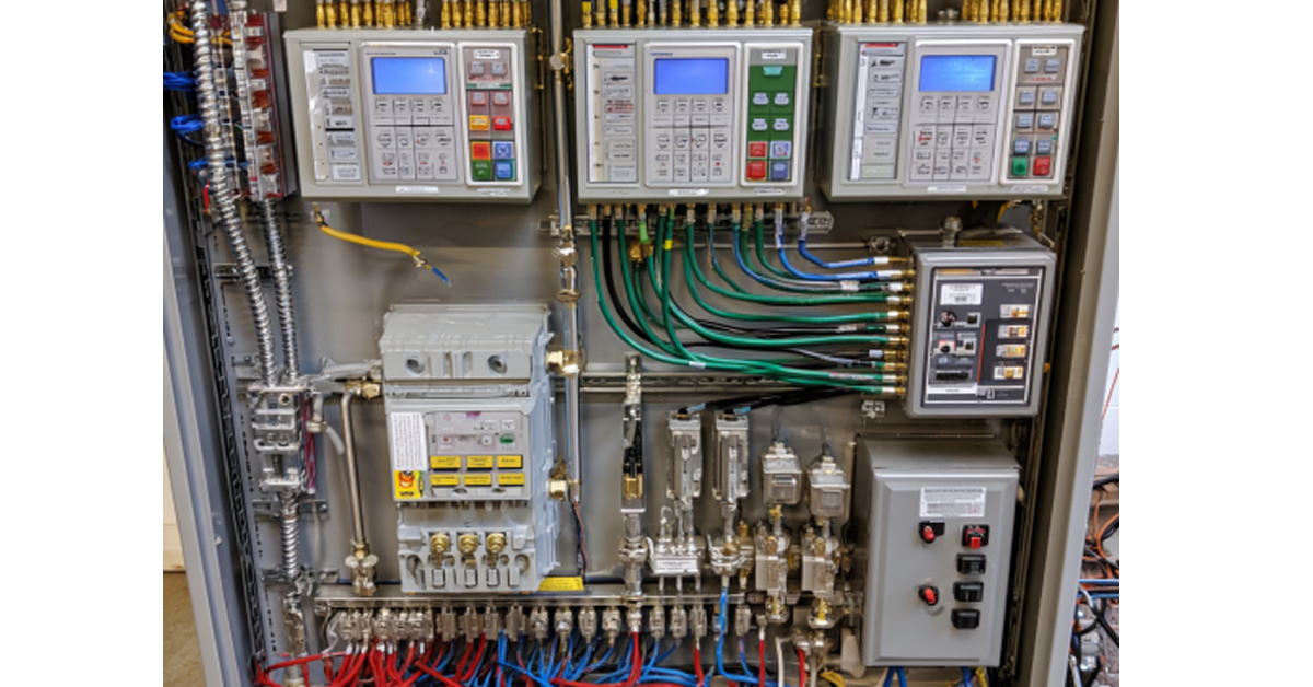
A packaged mechanical system with a single-point electrical connection has one power supply connection point on the exterior of the system. The installation electrician runs one circuit from the building electrical panel to that connection point. Everything inside the system, pumps, motors, VFDs, control panels, space heaters, lighting, instrumentation, and any other electrical components, is wired internally at the factory.
The alternative is a system where each electrical component requires its own field connection. The pump motors connect directly to the building electrical system. The VFDs connect separately. The control panel connects separately. The space heater connects separately. Each of those connections requires conduit, wire, terminations, and inspection. Each is a potential installation error. Each requires coordination between the mechanical contractor and the electrical contractor on site.
The single-point connection eliminates that complexity. The internal wiring is done in the factory under controlled conditions with full quality documentation. The field work is one connection and a verification that the system powers up correctly.
For the single-point connection to work correctly, the specification needs to define the incoming power requirements clearly. Voltage, phase, frequency, and amperage. The packaged system’s internal distribution panel is designed around these parameters. If the available power at the installation site differs from the specified parameters, the internal panel design needs to be adjusted before fabrication, not after the system arrives on site.
What single-point piping connections mean
A packaged mechanical system with single-point piping connections has defined supply and return connection points on the exterior of the system for each fluid circuit. The mechanical contractor connects the building piping to these points and the system is hydraulically complete.
The alternative is a system where individual components have their own field piping connections. Each pump has its own inlet and outlet connections. Each heat exchanger has its own supply and return connections. Each ancillary system, expansion tank, chemical feed, glycol feed, has its own connections. The mechanical contractor assembles all of these connections in the field, making the installation as complex as a field-built system.
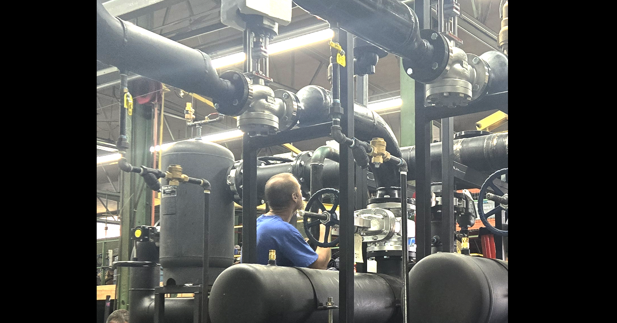
Single-point piping connections require that all of the internal piping, including headers, manifolds, isolation valves, check valves, and any other internal piping components, be completed at the factory. The field connections are limited to the defined tie-in points on the system boundary.
The specification needs to define the connection sizes, locations, and orientations before fabrication begins. Connection size needs to match the building piping. Connection location needs to be accessible for the mechanical contractor to make the connections without removing panels or disassembling surrounding structure. Connection orientation, whether the connections face up, down, or to the side, needs to match the direction the building piping approaches the system.
What single-point controls connections mean
A packaged mechanical system with single-point controls connections has a defined interface point for the building automation system. The controls contractor connects the BAS to this single interface and the system communicates with the building controls infrastructure.
Internally, all of the controls wiring between components is completed at the factory. The sensors, the actuators, the VFD control signals, the status outputs, and the alarm contacts are all wired to the system’s control panel before the system ships. The field controls work is limited to connecting the BAS interface.
The specification needs to define the BAS communication protocol before fabrication begins. BACnet, Modbus, LonWorks, and proprietary protocols all require different hardware configurations in the control panel. Defining the protocol after the panel is built requires a panel modification that adds cost and schedule. Defining it before fabrication begins is a question that takes minutes to answer and costs nothing.
How to specify single-point connections correctly
The specification language for single-point connections needs to be explicit. Saying a system should be factory assembled does not automatically mean it will have single-point connections. The fabricator needs to know that single-point connections are required and what the parameters of each connection are.
For electrical, specify the incoming power voltage, phase, frequency, and amperage. Specify that all internal wiring shall be completed at the factory and that the system shall have a single power supply connection point accessible from the exterior of the system.
For piping, specify the connection sizes, the connection locations by reference to the system orientation, and the connection orientations. Specify that all internal piping including headers, valves, and ancillary system connections shall be completed at the factory and that field connections shall be limited to the defined tie-in points.
For controls, specify the BAS communication protocol and the signal types required. Specify that all internal controls wiring shall be completed at the factory and that the BAS interface shall be accessible from the exterior of the control panel.
FabPro Systems builds single-point electrical, piping, and controls connections into every packaged system as standard practice. The documentation that ships with every FabPro system includes a connection schedule that identifies every field connection point, the required connection parameters, and the internal components that connection serves. When the installation team arrives on site, the connection schedule tells them exactly what connections need to be made and in what sequence.
For packaged systems that include Wilo or other pumps represented by Merion Pump Company, the pump selection and performance data are coordinated between Merion and FabPro during the design process. Visit merionpump.com for more on Merion’s commercial pump capabilities. For systems connected to commercial boiler plants, the GP Energy Products team handles the boiler side of that conversation. Visit gpenergyproducts.com for more on GP Energy’s boiler capabilities.
FabPro Systems designs and fabricates custom packaged mechanical systems for commercial, institutional, and industrial applications nationally. If you have a packaged system application in development and want to make sure the connection configuration is specified correctly before fabrication begins, reach out and we will work through the connection requirements with you.
References
1. NFPA 70. National Electrical Code. Covers electrical panel design, wiring methods, and single-point connection requirements for packaged mechanical systems. nfpa.org
2. NEMA. Standards for Industrial Controls and Systems. Covers control panel design, wiring termination, and documentation requirements for factory-assembled control systems. nema.org
3. ASME B31.3. Process Piping Code. Governs pressure testing and documentation requirements for factory-assembled piping systems. asme.org
4. ASHRAE. Commissioning Process for Buildings and Systems, Guideline 1.1. Covers factory testing documentation and the relationship between factory-assembled system documentation and field commissioning. ashrae.org
All technical claims are consistent with the standards listed above. Confirm site-specific electrical, piping, and controls requirements with the engineer of record before finalizing the packaged system specification.




Leave A Comment